Cedar Porch Balustrade Structural Testing
American Porch Wood Porch Rail Systems passed testing according to ASCE (American Society of Civil Engineers) building code guardrail requirements.
An independent third party conducted porch balustrade structural testing on our 4″ Porch Rail System and 6″ Porch Rail System, which were installed on the testing fixture with our Rail Installation Kit, Newel Posts, and Newel Installation Kit. The products were installed on the testing fixtures using the instructions listed on our Wood Balustrade Installation Instructions page. The guardrail standard used was the ASCE Standard for “Minimum Design Loads for Building and Other Structures” section 4.5.1 Loads on Handrail and Guardrail Systems. This standard was chosen because it exceeds the requirements called for by the IRC and IBC codes, meaning if it passed the ASCE standard, then it passes also the International Residential Code and International Building Code requirements. The 4″ and 6″ Rail Systems, along with the Spindles, Newel Posts, Rail Installation Kit hardware, and Newel Post Installation Kit hardware, used together were all found to pass all requirements.
For the test, we provided materials that would be a “worst case scenario”, meaning the longest, highest rail systems we sell. So we provided 12′ sections of balustrade, at a 42″ top rail height (the highest we offer as standard items), and the thinnest spindles recommended for those systems (1 5/8″ and 2 1/2″ wide for the 4″ and 6″ Systems respectively). This means the balustrade would be at it’s greatest disadvantage during the test.
We are very proud to have our proprietary wood railing systems independently tested for guardrail requirements. Normally, wood rail is covered in the codes under a generic wood rail heading. But we wanted to prove that our products and associated hardware is designed with superior engineering. There was a lot of Research & Development that went into these materials and hardware. It’s been a lot of work, and we’re happy to put our products, literally, “to the test”.
To download the test report click Wood Balustrade Structural Testing (PDF)
Or view the complete test report below:
CENTER FOR ADVANCED MINERAL, METALLURGICAL AND MATERIALS PROCESSING
Montana Tech
1300 West Park Street
Butte, MT 59701
406-496-4808
ASCE Testing of 6in and 4in Rails
8/20/18
PREPARED FOR:
Western Spindle, LLC
310 6th St. Townsend, MT 59644
PREPARED BY:
Taylor O. Winsor
The Center for Advanced Mineral, Metallurgical and Materials Processing (CAMP) was contracted by Western Spindle to characterize two sets of rails. All testing was performed within the CAMP Wood Structures Lab, located on the Montana Tech campus in Butte, Montana. The two rails were referred to as the 6in and 4in hand rail and are identified in Table 1.
Table 1: Test Material Identification
| Sample Identity | Sample Attributes |
| 6in Rail | 12ft, 6in top rail, 7 ¾” x 7 ¾” post |
| 4in Rail | 12ft, 4in top rail, 5 ¼” x 5 ¼” post |
The two rails were tested in accordance to ASCE Standard for “Minimum Design Loads for Buildings and Other Structures” section 4.5.1 Loads on Handrail and Guardrail Systems. The standard outlined three tests, a 50lb/ft. distributed load, a 50lb on a 12in x 12in max section on the spindles, and a 200lb single pt. at worst case, the tests where done in the order mentioned. The rail was considered to pass if no catastrophic failure occurred during the loading/unloading, damage to the structure or the hardware that was not catastrophic was deemed acceptable.
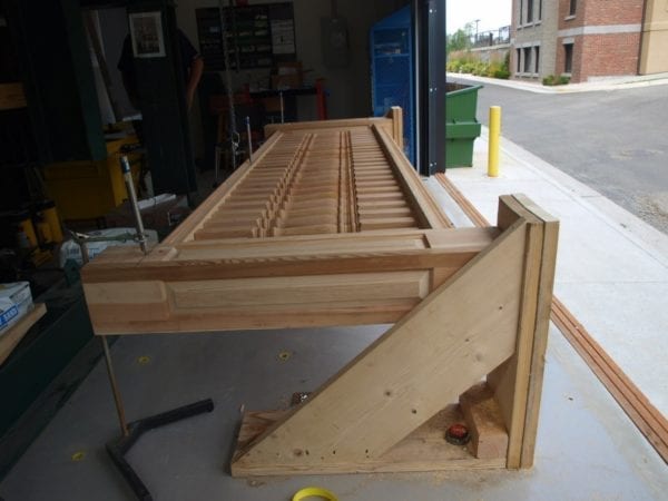
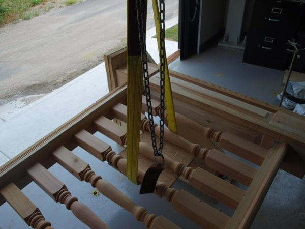
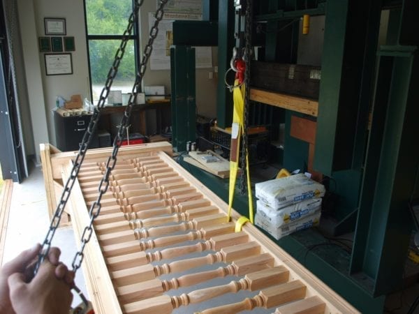
The rails were mounted in a horizontal position so the team could use gravity to simulate the distributed load. The other two test pulled the rail in the opposite direction of gravity, the fixture used and set-up is depicted in Figure 1.
Figure 1: Set-up & fixture for rail testing
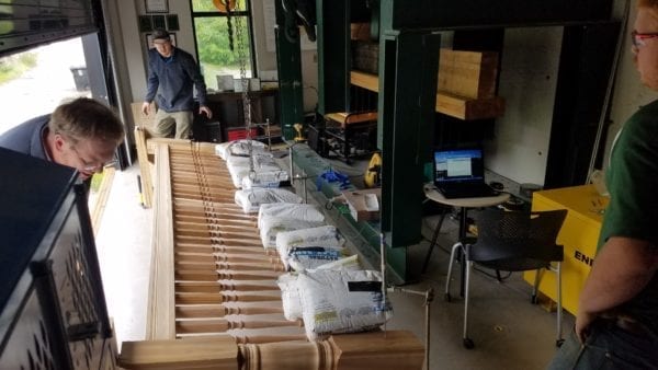
50lb/ft. Distributed Load
The distributed load was simulated by using 12 – 50lb sand bags, with two bags being added at a time and 10-15 seconds for the structure to settle and data collected before the next sand bags where added. The sand bags were first added at the center of the rail, and then placed further from center as the number of bags increased. The displacement at both ends of the rail as well as the center were measured using LVDT’s, the two ends were averaged to be reported. The max displacement of the LVDT’s were 5in, therefore any deflection reporting 5.00 means the actual deflection was 5.00in or greater. Due to the means for calibration, the low end accuracy is poor and is reflected by the values being greater than zero at no load. Table 2 and 3 depict the deflection from the load at the mid and full span for the 6in and 4in rail respectively.
Table 2: Deflection of the 6in rail – 50lb/ft. distributed load
| Load (lb.) | Mid Span Deflection (in) | Avg. Full Span Deflection (in) |
| 0 | 0.18 | 0.19 |
| 100 | 0.34 | 0.19 |
| 200 | 0.86 | 0.24 |
| 300 | 1.50 | 0.44 |
| 400 | 2.19 | 0.86 |
| 500 | 3.30 | 1.78 |
| 600 | >5.00 | 3.56 |
Table 3: Deflection of the 4in rail – 50lb/ft. distributed load
| Load (lb.) | Mid Span Deflection (in) | Avg. Full Span Deflection (in) |
| 0 | 0.18 | 0.19 |
| 100 | 0.84 | 0.28 |
| 200 | 1.74 | 0.52 |
| 300 | 3.09 | 1.24 |
| 400 | >5.00 | 2.93 |
| 500 | >5.00 | 4.72 |
| 600 | >5.00 | >5.00 |
Figure 2 & 3 are the 6in and 4in respectively at the full load during the distributed load test. Both rails had hardware deformation and cracking in the posts. Due to the lack of catastrophic failure the rails were deemed to have passed.
Figure 2: 6in rail at full load of 600lbs during the distributed load test
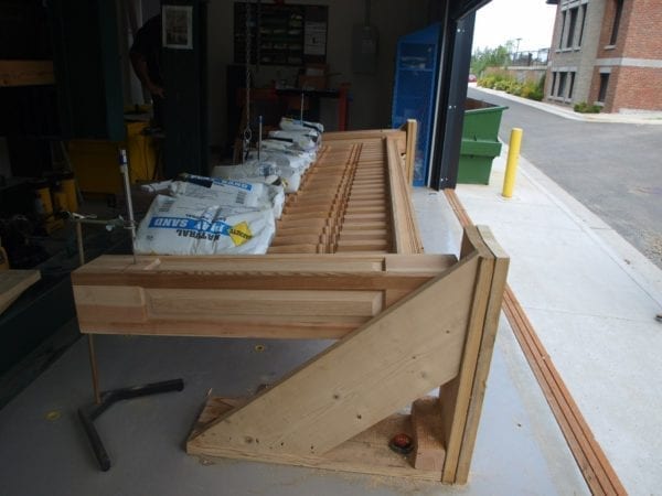
Figure 3: 4in rail at full load of 600lbs during the distributed load test
50 lbs. on a 12in x 12in Section of the Spindles
A 12” x 12” plywood plate was placed under a section of spindles, which covered three spindles for both the 6in and 4in rails, and a 50lb proof load was applied in the upward direction. Both rails passed with no cracking or major distortion of spindles or hardware. The test was continued to record the load required to break the spindles. The 6in rail spindles did not failure due to fear of failing the whole rail prior to the 200lb worst case proof load test and was stopped at 900lbs. Table 4 summarizes the spindle tests while Figure 4 shows the test set-up.
Table 4: 12” x 12” spindle failure loads
| Rail | # of spindles | Spindle Max Load (lb.) |
| 6in | 3 | 900* |
| 4in | 3 | 328 |
*Not a Failure
Figure 4: Set-up for the 50lb – 12” x 12” spindle tests
200lb Point Load at Worst Case Scenario
The ASCE standard calls for a 200lb worst case scenario point load, this load was applied in the vertical direction at the mid span, at the hand-rail, putting the load the furthest from the support to maximize the stresses. Both the 6in and 4in passed the 200lb proof load and the test continued to record the max load. Table 5 indicates the max loads and the failure mechanism for both rails, while Figure 5 depicts the test set-up.
Table 5: Summary of full load, worst case testing
| Rail | Max Load (lb.) | Failure Mechanism |
| 6in | 860 | Post member failure and separation |
| 4in | 380 | Weld fail at nut of mounting hardware |
Figure 5: Set-up of worst case scenario testing
Summary of Rail Testing
| Test type | Load (lb.) | Pass / Failure |
| 6in Rail | ||
| 50lb/ft. Dist. Load | 600 | Pass |
| 50lb / 12”x12” Spindle | 900 min | Pass |
| Worst Case Pt. Load | 860 | Pass |
| 4in Rail | ||
| 50lb/ft. Dist. Load | 600 | Pass |
| 50lb / 12”x12” Spindle | 328 | Pass |
| Worst Case Pt. Load | 380 | Pass |
All results and material properties pertain only to the samples submitted by Western Spindle. If any questions or feedback arise concerning the testing or this report, please contact Taylor O. Winsor at 206.819.6309 or by email at [email protected].
C.A.M.P. C.A.M.P.
Taylor O. Winsor Ronda Coguill
Quality Manager Lab Manager